
Limit Switch Testing
| The limit switch is a normally closed switch in series with the sail switch and the thermostat. Being temperature actuated, it is designed to "snap open" when an over temperature condition occurs. Thus the switch is normally opening under full load conditions and that causes arcing of the contacts. Over a period of time the contacts can become pitted, corroded or intermittent. It is easy enough to just replace the old limit switch! However, if you don't have one handy, it's also easy enough to check the performance of the old switch. When the switch is closed, the contact resistance as measured with any decent Ohmmeter, digital or analog, should be less than a tenth (0.1) of an Ohm. The maximum current that flows through the switch is the current taken by the circuit board plus the current taken by the gas valve assembly. Normally this total is less than 1 amp. The maximum of 1 amp and 0.1 Ohms is a maximum voltage drop of 0.1 volts across the switch. Several testing methods can be used to check the limit switch. |
Test method 1: The preferred (but not always the easiest) method
by Philip Armstrong
| With the furnace in full operation, connect a digital voltmeter across the two connections of the limit switch. The voltage drop should be less than or a maximum of 0.1 VDC. The switch should be immediately suspect if the voltage drop is 0.2 VDC or higher (Fig. 1 indicates a bad limit switch). |
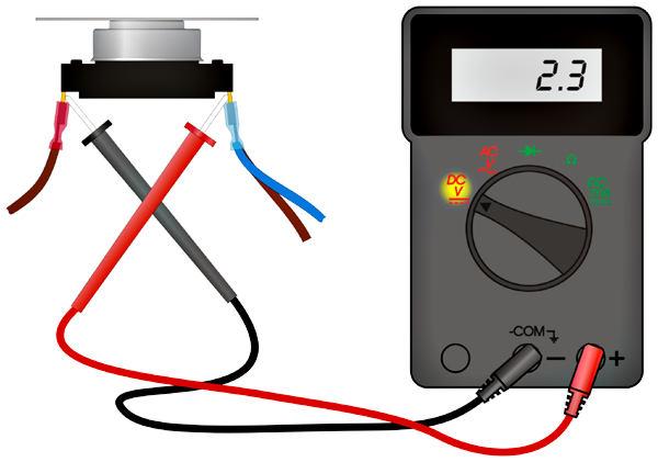 Fig. 1)
Test method 2: Using an Ohmmeter
| Verify that your ohmmeter will read "0" when the two leads are shorted together. The meter should read between "0" and "0.1" Ohms. Remove the switch or at least disconnect the wires from it and connect an Ohmmeter-set it to the lowest possible range-across the switch. Now depress and release the snap action surface of the switch a dozen or so times. Each time you press on it, the switch should go from OPEN to CLOSED with each closure being a reliable 0.1 Ohms or less. Anything higher is cause for replacement (Fig. 2 shows a good switch). |
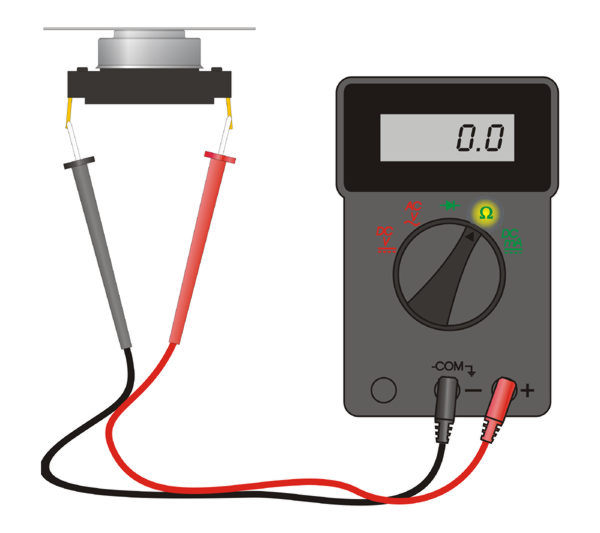 Fig. 2)
Test method 3: Using a battery operated continuity tester
| Using a continuity tester with a built in battery and lamp - the one we used has two AA cells and when the batteries are new, the current through the switch is about 0.29 Amps. With the continuity tester connected across the limit switch (Fig. 3), the light should be just as bright as when the continuity tester leads are shorted together. Do the OPEN and CLOSED test as described in the Ohmmeter test procedure and the light should be the same brightness for each OPEN and CLOSE sequence. The test light method is the least preferred test procedure because you just cannot detect the minute variations with the light that you can with a meter. |
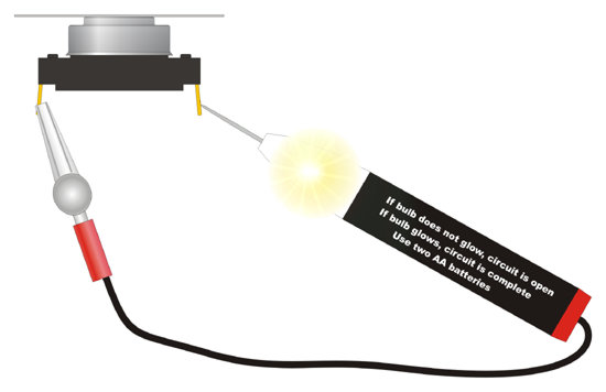 Fig. 3)